


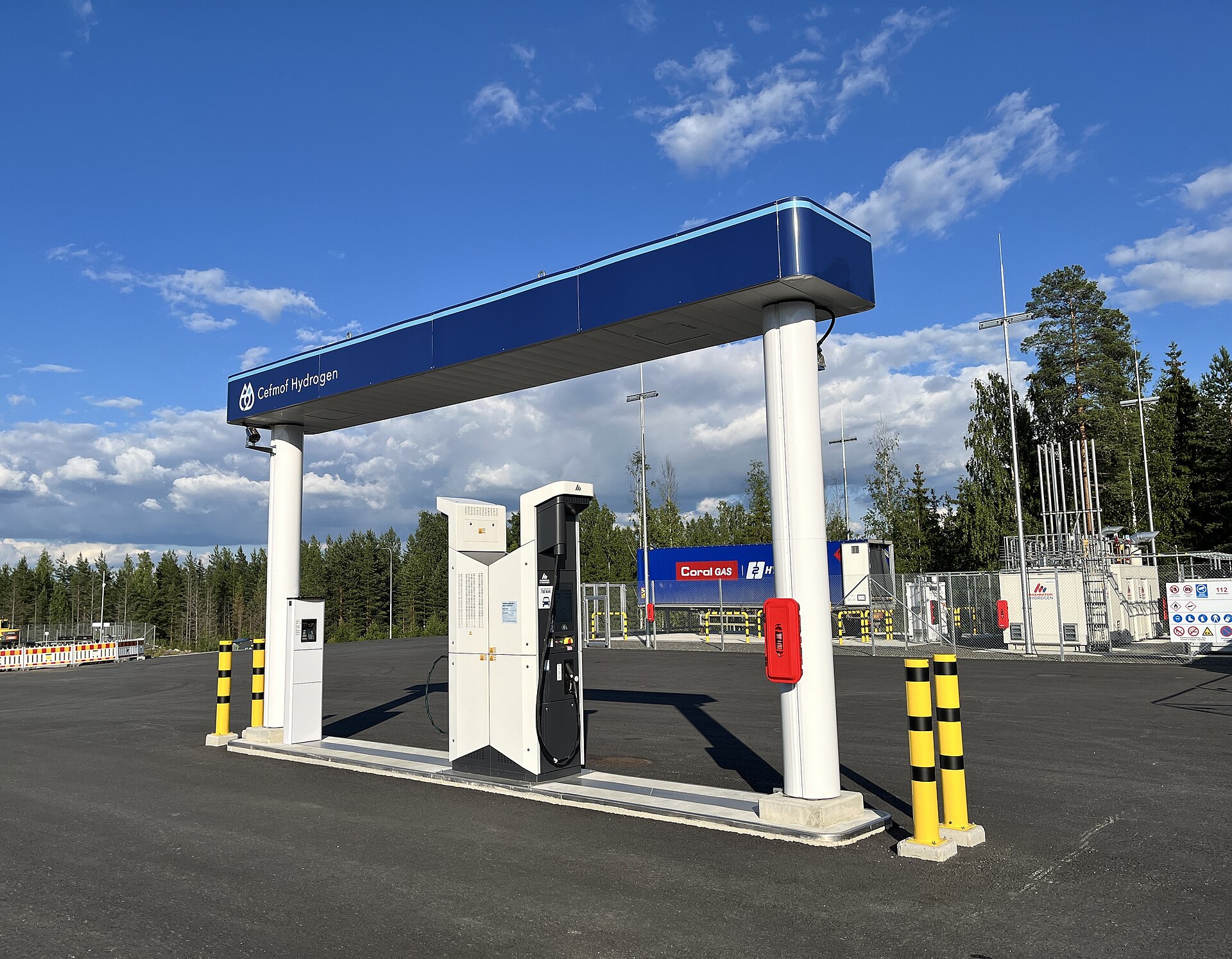


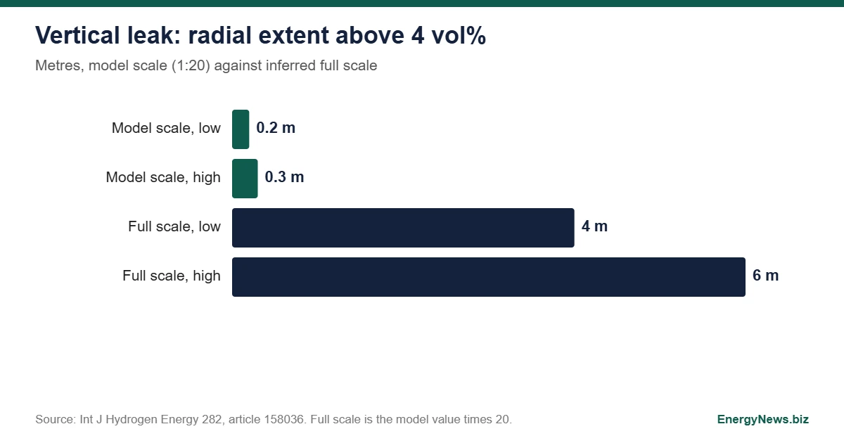
Hydrogen leakage in a refuelling area is dangerous because the gas ignites with as little as 0.017 mJ, and the flammable range runs from 4 to 75 volume percent. A new experiment in the International Journal of Hydrogen Energy puts the region above 4 percent for a vertical upward release at about 4 to 6 m at full scale. That number is inferred from a 1:20 model that used helium, and it describes a still, uncluttered question: where a sensor has to be to see a leak early.
The study fills a gap its authors identify in the literature. Most work on refuelling stations is numerical, experiments simplify the layout, and the few full scale tests focus on the explosion after ignition. A statistical review the paper cites counted 43 leakage accidents at refuelling stations, 10 of them linked to the dispenser and its components, mainly seal failures or insufficient torque at hose connections. The dispenser area is where leaks start, and it is the area the new model reproduces.
Why helium, and why 1:20
The team built a 1:20 model of a refuelling area with the actual equipment layout and used helium as a stand in for hydrogen. They state that the Reynolds, Froude and Richardson numbers should be kept consistent between model and station so that viscous, inertial and buoyancy forces scale correctly. They varied leakage duration (30, 60 and 90 seconds), direction and flow rate, and measured concentration at a set of monitoring points including ceiling sensors.
The abstract does not give the release pressure or the equivalent full scale flow rates. That matters because the 4 to 6 m figure comes from multiplying the model length by 20: the high concentration region measured about 20 to 30 cm in radius at model scale. The 50 percent spread between the two ends of that range is the real uncertainty in the headline, and it is larger than any rounding.
Three stages, and a duration that does not change the peak
Concentration at the monitoring points went through three stages: rapid growth, stable development and decay. Leakage duration had limited effect on peak concentration but prolonged how long high concentrations persisted. For safety design that separates two questions. How high a concentration can reach depends mainly on release rate and geometry, and how long it stays dangerous depends on how long the leak runs and how well the space clears.
A vertical upward release produced ceiling accumulation after the jet struck the canopy, and the normalized concentration decayed exponentially with dimensionless distance. A horizontal release promoted downstream dispersion and accumulation around obstacles. The same hydrogen leak therefore creates two different hazard maps depending on the direction in which the failed part points.
Where a sensor should sit
The authors conclude that sensors near the leak source responded fast to horizontal leakage, while ceiling sensors gave better coverage for vertical leakage. No single position covers both. A station designed around ceiling detectors would cover an upward jet better than a sideways release, and the reverse holds for sensors near the source. The paper proposes effective monitoring regions for each leakage condition, which is the part with direct engineering use.
What the number does not include
Four limits apply. Helium is a substitute, so the study measures dispersion and not combustion. The 4 percent threshold marks the lower flammable limit, so the region it defines is where ignition is possible, not where a damaging explosion is certain. The sections read for this analysis do not describe wind, and the paper’s own introduction notes that wind and surrounding structures strongly affect dispersion in numerical studies. And one layout was tested, so the result applies to that arrangement of dispenser and canopy.
The test for the 4 to 6 m figure is replication: measurements with hydrogen at station pressures, in the layouts of real stations and with wind, compared against the numerical models the authors say remain unvalidated. For a related safety question in pipelines, see why hydrogen blending risk peaks at 50 percent. Source: Yao and Tan, Experimental investigation of hydrogen leakage dispersion characteristics in a scaled hydrogen refueling area, International Journal of Hydrogen Energy 282 (2026) 158036. The work was funded by Beijing science programmes, and the authors declare no competing interests.
Add EnergyNews.biz as a preferred source on Google


